Technical Drawing Best Practices for Precision CNC Machining
When sourcing custom precision components, clear and detailed technical drawings act as the critical bridge between your design intent and the final machined part. Even with advanced 3D CAD models and modern CNC systems, a well-crafted 2D drawing remains irreplaceable for defining tight tolerances, surface finishes, and inspection criteria that directly impact quality, cost, and lead time.
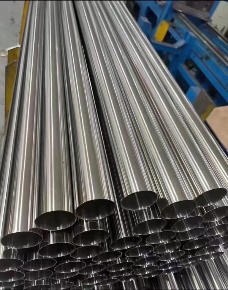
At Haomaer Precision, we specialize in delivering high-quality Swiss Machining Parts, Precision Turned Parts, Milling Parts, Multi-Axis Machining Parts, and Auto Lathe Parts for medical, aerospace, automotive, and industrial automation applications. In this guide, we walk you through the essential principles, key components, and step-by-step process to create manufacturing-ready technical drawings that eliminate misinterpretation and ensure consistent production results.
Why Technical Drawings Matter for Precision Machining
A 3D CAD model defines the ideal geometry, but it cannot fully communicate the allowable variations, surface requirements, or quality standards critical for precision manufacturing. A comprehensive 2D technical drawing serves five core purposes:
- Define Critical Tolerances: Specify acceptable deviations for dimensions and geometric features, ensuring parts fit and function as intended.
- Specify Surface Finishes: Clearly indicate roughness values (e.g., Ra 0.8 µm) that affect performance, corrosion resistance, and cost.
- Communicate Special Instructions: Detail threading, knurling, heat treatment, or plating requirements not modeled in 3D.
- Ensure Quality Control: Provide inspectors with definitive criteria for verifying part accuracy and compliance.
- Avoid Costly Miscommunication: Reduce errors, rework, and delays by aligning design and manufacturing expectations.
For high-precision applications like Swiss Machining Parts or Multi-Axis Machining Parts, where tolerances can be as tight as ±0.001mm, a precise drawing is not just helpful—it is essential.
Key Components of a Manufacturing-Ready Technical Drawing
A technical drawing combines standardized visual elements and textual information. Mastering these components ensures your designs are interpreted correctly by machinists and inspectors worldwide.
1. Standard Line Types
Each line type conveys specific information about the part’s geometry:
- Visible Lines: Thick solid lines showing outer edges.
- Hidden Lines: Thin dashed lines representing obscured features.
- Center Lines: Alternating long/short dashes marking symmetry or circular feature axes.
- Dimension Lines: Thin solid lines with arrows defining measurements.
- Section Lines: Angled hatching indicating cut material in cross-sections.
2. Orthographic Views (Primary Projections)

Orthographic projection is the global standard for representing 3D objects in 2D without distortion. A complete drawing includes three primary views:
- Front View: The most descriptive face, placed centrally.
- Top View: Directly above the front view, showing length and width.
- Side View: To the right of the front view, showing height and depth.
Always confirm the projection standard: First Angle (Europe/Asia) or Third Angle (USA/Canada)—misinterpretation can lead to reversed parts.
3. Supporting & Specialized Views
Complex parts require additional views to clarify details:
- Isometric View: A 3D pictorial view for intuitive shape understanding.
- Section View: Reveals internal features (holes, cavities) by cutting through the part.
- Detail View: Magnifies small, intricate areas for clear dimensioning.
- Exploded View: Shows assembly relationships for multi-component parts.
4. Dimensions & Tolerances (The “Soul” of the Drawing)

Dimensions define the size and location of every feature, while tolerances specify acceptable variation.
- Key Dimensions: Overall size, critical lengths, diameters, and hole positions.
- Tolerance Types:
- General Tolerances: Applied to all unspecified features (e.g., ISO 2768-m).
- Specific Tolerances: Tighter limits for critical features (e.g., 10.00 ± 0.02 mm).
- GD&T: Geometric tolerances for form, orientation, and position control.
DFM Best Practice: Only apply tight tolerances to critical features—overly strict requirements increase machining time and cost.
5. Essential Information Blocks
These blocks provide administrative and manufacturing context:
- Title Block: Bottom-right corner with part name, number, revision, material, scale, units, and general tolerances.
- Notes Block: Special instructions (deburring, surface finish, standards).
- Bill of Materials (BOM): For assembly drawings, listing all components.
Common Types of Technical Drawings
1. Part Drawing (Detail Drawing)
A standalone document for a single component, used for manufacturing. It includes complete views, dimensions, tolerances, material specs, and finish requirements—essential for producing Precision Turned Parts or Milling Parts.
2. Assembly Drawing
Shows how multiple components fit together. It features exploded views, balloons linking parts to a BOM, and overall dimensions—used for assembling multi-part assemblies.
10 Steps to Create a Perfect Precision Machining Drawing

Follow this structured process to ensure your drawings are clear, complete, and manufacturing-ready:
Step 1: Select a Standard Template
Start with ISO, ASME, or a company-specific template with predefined borders, title blocks, and coordinate systems.
Step 2: Arrange Primary Orthographic Views
Place front, top, and side views following the correct projection standard, leaving space for dimensions.
Step 3: Add Section and Detail Views
Include sections for internal features and details for small, complex areas.
Step 4: Insert an Isometric View
Add a 3D isometric view to help machinists visualize the part.
Step 5: Add Center Lines and Symmetry Marks
Mark centers of holes, shafts, and symmetrical features.
Step 6: Dimension All Features Clearly
Use baseline dimensioning, avoid duplication, and group related dimensions.
Step 7: Specify Holes, Threads, and Critical Features
Clearly define hole sizes, depths, thread types, and special features.
Step 8: Apply Tolerances Strategically
Assign general tolerances for standard features and specific tight tolerances for critical surfaces.
Step 9: Complete the Title Block and Notes
Fill in all administrative data and add special instructions (deburring, plating, inspection).
Step 10: Review and Validate
Double-check for missing dimensions, inconsistent tolerances, or ambiguous notes. Ensure the drawing can be understood by a machinist unfamiliar with the part.
Conclusion
A well-prepared technical drawing is more than a document—it is a precision communication tool that aligns design intent with manufacturing execution. By mastering standard components, following best practices, and leveraging the expertise of a reliable partner like Haomaer Precision, you can ensure your Swiss Machining Parts, Precision Turned Parts, Milling Parts, Multi-Axis Machining Parts, and Auto Lathe Parts meet your exact specifications for quality, precision, and performance.
Need help translating your design into manufacturing-ready technical drawings? Contact Haomaer Precision today for expert guidance and high-quality precision machining solutions tailored to your application.